Original Link: https://www.anandtech.com/show/6511/gigabyte-f2a85xup4-review-are-powirstages-needed-with-trinity
Gigabyte F2A85X-UP4 Review – Are PowIRStages Needed with Trinity?
by Ian Cutress on December 14, 2012 12:00 PM EST- Posted in
- Gigabyte
- Motherboards
- FM2
- A85X
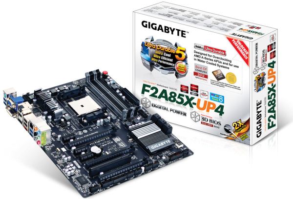
Since Computex back in June, Gigabyte has been pushing a new power delivery system across parts of its motherboard range. This involves an integrated circuit to combine power delivery MOSFETs into a small form factor with great heat dissipation, high efficiency and a smaller PCB space – the PowIRStage IC3550 they have been using is rated up to 60A of current each. This makes sense in the high end spectrum (Z77X-UP7) where power might be needed, or in low airflow situations (mITX) to ensure longevity. But is it required on a desktop Trinity board? These things are expensive, which made me wonder if it is a worthwhile investment in a desktop Trinity system. Read on for the full run-down of the F2A85X-UP4.
Gigabyte F2A85X-UP4 Overview
Very rarely does a motherboard ever just ‘work’. Normally there is a little issue here or there, but looking back on the notes I made while testing, nothing significant came up while testing the Gigabyte F2A85X-UP4. However, ultimately the goal of a motherboard should be to bring something new to the table – the concept of a board ‘doing everything it should do out of the box’ has to be the standard, not the exception.
The F2A85X-UP4 brings a little more to the Trinity platform than some of its competition. PowIRStage IR3550 ICs, which we have detailed in previous reviews, are used and for a minor increase in cost we get a fewer phases rated at a higher amperage that due to their design should provide a higher efficiency and run cooler than the previous premium power delivery ICs. Whether that increased cost is justified on a platform such as Trinity could be debatable, but Gigabyte insist that at least the high end board in each platform should have something similar. To take credence with the efficiency, the F2A85X-UP4 system draws the least power in our at-the-wall power tests.
Design wise we have enough PCIe slots for three GPUs in CrossFireX (no SLI, not certified), seven SATA 6 Gbps ports on board, a TPM header, DualBIOS methodology, power/reset buttons, a debug LED, the Realtek ALC892 audio codec and a Realtek 8111E NIC. Two extra USB 3.0 ports are also supplied through an Etron EJ168 controller.
The A85X platform in Gigabyte’s hands uses their 3D-BIOS system, which over the previous year we have detailed almost to excess. The software on the platform is seemingly limited, with EasyTune6 showing its age and not giving any automatic overclock settings. In terms of manual overclock, our board performed up to 4.5 GHz on default LLC before voltages required for stability got a little crazy.
In terms of performance, the Gigabyte F2A85X-UP4 sits well with the rest of the pack of FM2/A85X boards we have reviewed so far. As mentioned previously, the place it really excels seems to be in terms of power usage at idle, during CPU load and during dual GPU gaming. In the box we get a couple more SATA cables than in other FM2/A85X packages.
For $130 the Gigabyte F2A85X-UP4 is pushing the upper limits in terms of Trinity motherboard pricing, but with the PowIRStage IR3550s being used to increase stability while decreasing power dissipation, it is clear to see why. While it does not surpass any of the competition (some would argue it is at a lower price:performance ratio), it falls into the category of a rare board that passes my desk without any serious issues, and it should be seriously considered as a reliable purchase.
Visual Inspection
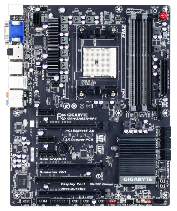
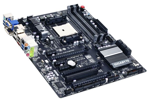
What struck me most about the UP4 over other motherboards is the lack of heatsink covering the power delivery. In most motherboard designs we typically see a multi-ridged heatsink oriented both above and to the left of the CPU socket area, possibly with a heatpipe connecting down to the chipset heatsink. On the UP4, due to the ‘UP’ in the name, Gigabyte has used Ultra Durable 5. To the system builder, this means PowIRStage IR3550 ICs which are reported to reduce VRM temperatures by up to 10-20°C in limited airflow environments over previous high-end solutions. The additional cost of these ICs (which should in turn give lower RMA rates) is slightly offset by the reduction in cost of the smaller heatsink over something larger, and that these ICs are rated at 60A and thus fewer should be required on board. But there is still an overall premium from using the upgraded power delivery.
In terms of fan headers this board gets five - all 4-pin. The CPU fan header is located underneath the power delivery heatsink, and around the socket a SYS fan header is above the power delivery heatsink. Two of the fan headers are next to the 24-pin ATX power connector, and the final one is on the bottom of the board. Ideally I would have preferred one of the headers moved to where the CPU fan header is to allow for multi-fan setups. Nonetheless, the socket area is very clean for any manner of large air cooler.
The memory slots unfortunately do not use a single latch system; though to the top right of them we have a large power button in red flanked by two smaller buttons for reset and clear CMOS. On the right hand side of the board underneath the 24-pin ATX power connector we have a USB 3.0 port powered by the chipset, and six black SATA 6 Gbps ports. The FM2 chipset supports eight of these ports, so Gigabyte has located the seventh on the bottom of the board at a different angle and the eighth on the IO panel in the form of eSATA. All the SATA ports support RAID 0, 1, 5 and 10, meaning that this FM2 setup is good for a single OS drive and a 6-drive RAID 5 storage array. Below the SATA ports are two BIOS chips for Gigabyte’s DualBIOS, and a two-digit debug.
Along the bottom of the board is our usual array of fixtures on a Gigabyte product – a TPM header, a COM header, four USB 2.0 headers (one with quick charging), front panel audio, a front panel header, a fan header and a SATA port.
The PCIe layout is beneficial to dual GPU users with a PCIe x1 sound card – the GPUs can go into the top two full length PCIe lanes and the sound card can go in either the top port or between the cards. In order we have an x1, x16 (x8 in dual), x1, x1, x8, PCI, x4 (from the chipset). This final PCIe slot is routed via the chipset, and thus will cause this x4 to have a higher latency than a standard x4 port.
For the rear IO panel we get a combination PS/2 port, two USB 3.0 from the chipset, a VGA, a DVI-D, an optical S/PDIF output, HDMI, DisplayPort, two USB 2.0, an eSATA 6 Gbps, a Realtek GbE, two USB 3.0 (Etron controller) and standard audio jacks. There is scope for improvement on the F2A85X-UP4 in that the VGA and DVI-D ports can be combined into a single DVI-I. This would allow the rear IO panel to take advantage of a more esoteric collection of ports.
Board Features
| Gigabyte F2A85X-UP4 | |
| Price | Link |
| Size | ATX |
| CPU Interface | FM2 |
| Chipset | AMD A85X |
| Memory Slots |
Four DDR3 DIMM slots supporting up to 64 GB Dual Channel, 1066-1866MHz |
| Video Outputs |
D-Sub DVI-D HDMI DisplayPort |
| Onboard LAN | Realtek 8111 |
| Onboard Audio | Realtek ALC892 |
| Expansion Slots |
2 x PCIe 2.0 x16 (x16/- or x8/x8) 1 x PCIe 2.0 x4 3 x PCIe 2.0 x1 1 x PCI |
| Onboard SATA/RAID |
7 x SATA 6 Gbps, Supporting RAID 0, 1, 5, 10 1 x eSATA 6 Gbps |
| USB |
4 x USB 3.0 Ports (Chipset) [2 back panel, 2 onboard] 2 x USB 3.0 Ports (Etron EJ168) [2 back panel] 10 x USB 2.0 Ports (Chipset) [2 back panel, 8 onboard] |
| Onboard |
7 x SATA 6 Gbps 1 x USB 3.0 Header 4 x USB 2.0 Headers 5 x Fan Headers 1 x COM Header 1 x S/PDIF Output Header 1 x TPM Header Power/Reset Buttons Clear CMOS Button |
| Power Connectors |
1 x 24-pin ATX Power Connector 1 x 8-pin CPU Power Connector |
| Fan Headers |
1 x CPU (4-pin) 4 x SYS (4-pin) |
| IO Panel |
1 x PS/2 Combination Port 2 x USB 3.0 (Etron) 2 x USB 3.0 (Chipset) D-Sub DVI-D HDMI DisplayPort Optical S/PDIF Output 2 x USB 2.0 1 x eSATA 6 Gbps 1 x Gigabit Ethernet (Realtek) Audio Jacks |
| Warranty Period | 3 Years |
| Product Page | Link |
In order to compensate for using Ultra Durable 5 / IR3550 ICs, in order to meet a price point Gigabyte must rely on the Realtek ALC892 audio and a Realtek 8111 NIC. For specific applications, we often prefer the Intel NIC or the later version of Realtek audio, even though it comes at cost.
What I would actually like to see is a replacement chip for the iTE SuperIO controller. This chip is onboard to deal with some of the more legacy components, but it takes up a lot of space on the PCB that could be used for other things. This chip is either dirt cheap, or there is not a replacement available – but I would suggest that if the Realtek audio chip or Etron USB 3.0 controller is so small, then why is the iTE so large?
Gigabyte F2A85X-UP4 BIOS
When the concept of a graphical BIOS came into force, motherboard manufacturers had several ways of going about the issue. The main take on the matter was to skin an AMI or Award BIOS with a company logo, and dress up the options into an easier to read scenario. Some motherboard manufacturers took this a little further, giving easy mode options and representing some of the figures as bars and so forth. Every single manufacturer however missed a golden opportunity.
When something as complex as a BIOS is opened up to the world of software, magical things can happen. For a start, the BIOS can be made more interactive. None of this ‘press +/-‘ to change options, but actually representing the value in a different way. Take the fan control options used in most software models today – we get gradient inputs, sometimes multi-point gradients, sometimes hysteresis. This is perfectly suited for a BIOS, and yet no motherboard manufacturer has thought to go down this route, with the interpolation done on the side of software. It amazes me quite a lot.
Part of the issue is space in the BIOS – typically modern motherboards use an 8 MB / 64 Mb BIOS chip which can be limiting if more and more features are being put in. This is partly why a BIOS is still a small screen size – if you wanted to put in a large image background, that could easily be 200kB-600kB depending on the complexity. These chips can cost as little as $0.30-$0.50 to be put on a motherboard, but that is part of the cost, and if a chip is needed that is 2x the size, it could be as much as 2x the cost. This is a double pain in the side of Gigabyte who insist that every motherboard up and down the range has two BIOS chips for their DualBIOS policy. I did once argue about making a BIOS chip like a microSD card reader allowing it to have 32GB+, but was immediately shot down due to the fact that something would have to initiate the microSD reader.
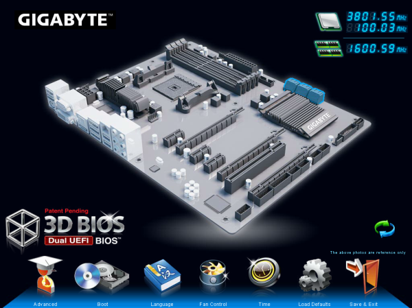
Back to the F2A85X-UP4, and Gigabyte use their 3D-BIOS design to greet us on the main screen:
To critique the front screen, it is highly annoying to say the least. As the image in the middle is not an actual representation of the motherboard at hand, there is no indication as to what model motherboard is being accessed. If we had this information, we would do not have to delve into the case to see what is what. Along with no motherboard name or BIOS version, there is no indication of the CPU model, nor the memory installed. These are basic things that should be in every BIOS, and hopefully Gigabyte will add them in due course.
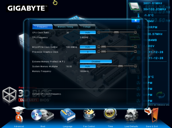
The oblique image on the front page is where the ‘3D’ part of the name comes from, and each area of the motherboard can be highlighted and clicked. For example, clicking the CPU section gives a portion of the full options in the advanced menu:
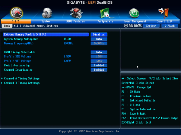
In the case of the CPU, we can change the BCLK, the CPU ratio and the memory timings from this tab, the memory sub-timings from tab 2 and the voltages from tab 3.
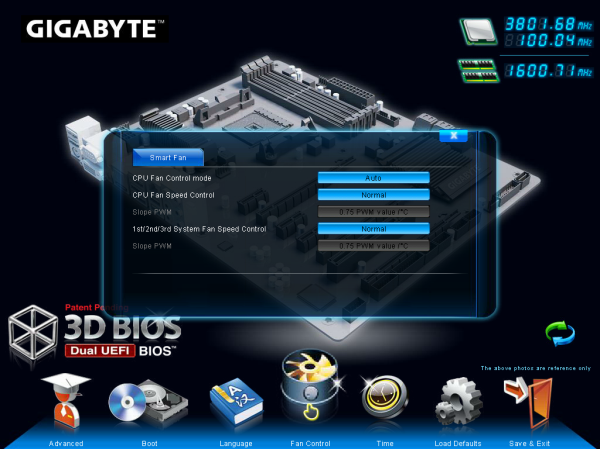
The fans can also be adjusted in the 3D BIOS by using the icon at the bottom. This gives the following options:
The fan headers on board are split into two categories – one for the CPU fan header and one for everything else. The fans can be manually adjusted in terms of PWM/ºC, which is a measure of power to the fan as a variation of temperature. As an expression of fan controls, this is absolute rubbish. Given that the system has inputs such as CPU workload and temperatures, the internal BIOS software should be able to convert any options a user selects into a form of ‘power X at temperature Y’ table in the BIOS to act on. The Gigabyte engineers know this as I have told them directly, and I hope it will be changed soon.
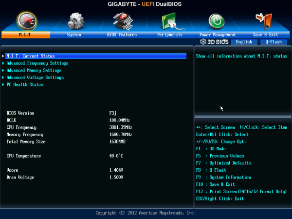
In the Advanced menu, we get a normal BIOS option interpretation:
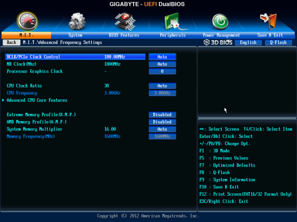
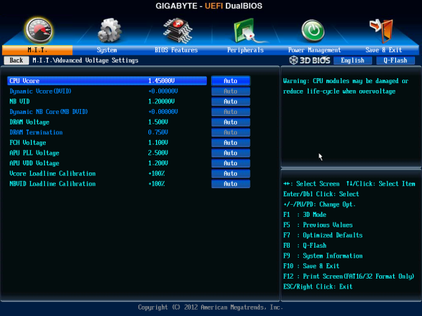
The Advanced screen here gives us more information about the product at hand than the 3D BIOS – namely the BIOS version, the CPU temperature and some voltage numbers. Most of the overclocking goes in the following menus, although the voltage options for the CPU and memory are in separate menus to the frequency settings.
The fan options are in the PC Health part of the main Advanced menu, but offer no more options than those in the 3D-BIOS. The boot options occur in the BIOS features menu, and the ability to turn on/off controllers comes through the Peripherals menu.
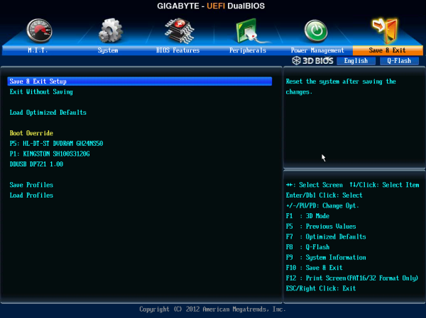
One plus point in the Gigabyte book is the boot override function, which allows for a one-time boot from a device. This is useful for installing an OS or running a monitoring program / ghosting.
Gigabyte F2A85X-UP4 In The Box
If the previous FM2/A85X packages are anything to go by, we should not expect much in the Gigabyte box. So far the previous packages have all contained four SATA cables, with the odd one or two adding extra connectors to aid the Front Panel connector placement.
In the Gigabyte F2A85X-UP4, we get:
Driver Disk
Manuals
Rear IO Panel
Six SATA cables
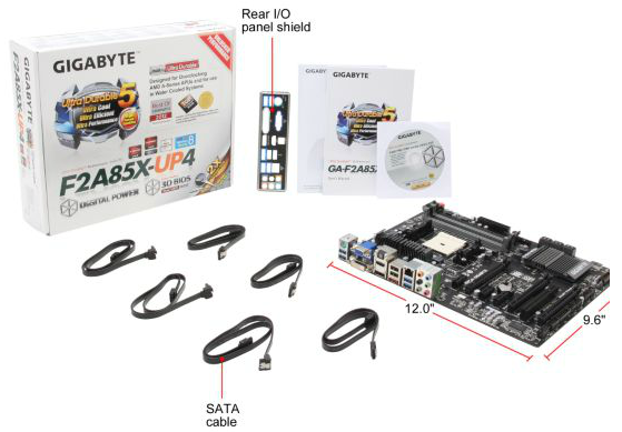
Gigabyte has a one-up on the other boxes so far, by virtue of two extra SATA cables. With a chipset that gives out eight SATA ports, having six in the box is a nice touch.
Gigabyte F2A85X-UP4 Software
The software stack at Gigabyte HQ is in a little bit of flux right now. On one hand they have software which has been part of the package for a few iterations, which we will examine later. On the other are extra bits of software that do not come on the install CD, but are available to download through the website. In an ideal world, the software would all be on the disk, and have an automatic updater included to download the latest releases of drivers and all software.
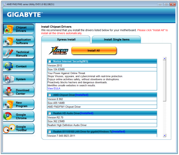
The Driver CD itself is easy to use – the first screen gives an option of deselecting software (such as the anti-virus) and an option to install everything.
After the driver and non-Gigabyte software install, another dialog appears asking if the user would like the Gigabyte utilities installed. Technically this should be singular, as only one utility is installed – EasyTune6.
EasyTune6
EasyTune has been with us in various guises over the years. The latest version is number six, which has been part of the main Gigabyte software package for at least two years now. The premise of EasyTune is simple – a single interface in order to get all the information about the system, perhaps do some overclocking, adjust some fan settings and monitor what is going in under the hood. While it is a nice goal, it leaves a little to be desired in terms of implementation.
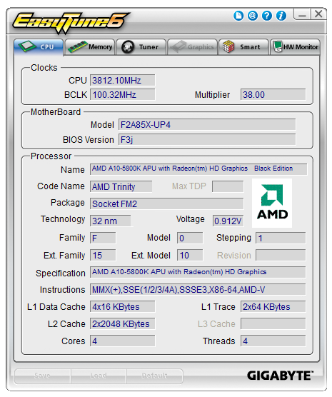
One element lacking in the land of Trinity processors with EasyTune6 is the options relating to automatic overclocking. It has been customary for Gigabyte to include several overclocking options in EasyTune for users to click one button and settings to be applied. No such luck – the only overclocking through ET6 is via the manual options. Users can adjust the BCLK, memory strap, base and turbo multipliers and also the voltages throughout the various menus.
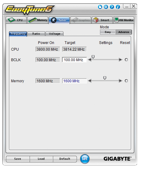
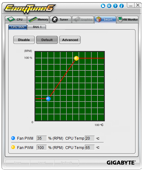
We can also control the fans in ET6, and this time we actually get a chance to play around with a gradient. This is only a two-point gradient, where the y-axis says RPM and the x-axis gives temperature. What is interesting is that below this are the actual numbers, whereby it says ‘Fan PWM, 35% (RPM)’. This is an erroneous statement – fan speeds are not directly proportional to the power applied. Typically a fan will start at a minimum RPM on low power, then after a threshold it will start to rise linearly. But not in the fashion that Gigabyte’s software suggests.
The final part of ET6 is the monitoring tool. This gives a small graphical output for voltages, although the scale of the graph could be frustrating as it tries to take into account low voltages such as the CPU along with the +12 V rail in the same graph. The default scan time of 3 seconds causes concern in our DPC Latency test, whereby we would score over 1000 microseconds when ET6 was running. This could lead to audio issues when recording, thus it is recommended to disable ET6 when audio processing.
Gigabyte F2A85X-UP4 Overclocking
Methodology:
Our standard overclocking methodology is as follows. We select the automatic overclock options and test for stability with PovRay and OCCT to simulate high-end workloads. These stability tests aim to catch any immediate causes for memory or CPU errors.
For manual overclocks, based on the information gathered from previous testing, starts off at a nominal voltage and CPU multiplier, and the multiplier is increased until the stability tests are failed. The CPU voltage is increased gradually until the stability tests are passed, and the process repeated until the motherboard reduces the multiplier automatically (due to safety protocol) or the CPU temperature reaches a stupidly high level (100ºC+). Our test bed is not in a case, which should push overclocks higher with fresher (cooler) air.
Automatic Overclock:
As mentioned above, the Gigabyte F2A85X-UP4 has no automatic overclocking methods. I am as shocked as you are, but the current Gigabyte policy is to only offer methods through ET6. As ET6 does not have any, all overclocking must be manual.
Manual Overclock:
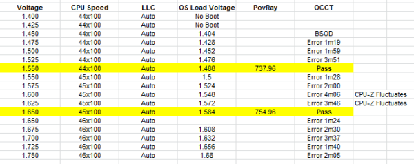
Using the BIOS, we took a similar approach to overclocking as with the other A85X motherboards tested with this processor. We start at 1.4 volts on the CPU in the BIOS and a CPU multiplier of 44x for all cores. Here are the results:
At 4.4 GHz we required a BIOS setting of 1.550 volts, which gave a load voltage in the OS of 1.488 volts. This passed OCCT and gave a PovRay score of 737.96.
At 4.5 GHz we required a BIOS setting of 1.650 volts, which gave a load voltage in the OS of 1.584 volts. This passed OCCT and gave a PovRay score of 754.96.
At 4.6 GHz, no setting was OCCT stable all the way up until 1.750 volts. This is higher than we have pushed any of our Trinity processors in other reviews, and thus I was uncomfortable pushing it further.
Many thanks to...
We must thank the following companies for kindly donating hardware for our test bed:
OCZ for donating the 1250W Gold Power Supply and USB testing SSD
Micron for donating our SATA testing SSD
G.Skill for donating our memory kits
ASUS for donating AMD GPUs and some IO Testing kit
ECS for donating NVIDIA GPUs
Test Setup
| Test Setup | |
| Processor |
AMD Trinity A10-4800K APU 2 Modules, 4 Threads, 3.8 GHz (4.2 GHz Turbo) |
| Motherboards |
ASUS F2A85-V Pro ASRock FM2A85X Extreme6 MSI FM2-A85XA-G65 Gigabyte F2A85X-UP4 |
| Cooling | ThermalRight Copper TRUE |
| Power Supply | OCZ 1250W Gold ZX Series |
| Memory | G.Skill TridentX 4x4 GB DDR3-2400 9-11-11 Kit |
| Memory Settings | 2133 9-11-11 |
| Video Cards |
ASUS HD7970 3GB ECS GTX 580 1536MB |
| Video Drivers |
Catalyst 12.3 NVIDIA Drivers 296.10 WHQL |
| Hard Drive | Corsair Force GT 60 GB (CSSD-F60GBGT-BK) |
| Optical Drive | LG GH22NS50 |
| Case | Open Test Bed - DimasTech V2.5 Easy |
| Operating System | Windows 7 64-bit |
| SATA Testing | Micron RealSSD C300 256GB |
| USB 2/3 Testing | OCZ Vertex 3 240GB with SATA->USB Adaptor |
Power Consumption
Power consumption was tested on the system as a whole with a wall meter connected to the OCZ 1250W power supply, while in a dual 7970 GPU configuration. This power supply is Gold rated, and as I am in the UK on a 230-240 V supply, leads to ~75% efficiency > 50W, and 90%+ efficiency at 250W, which is suitable for both idle and multi-GPU loading. This method of power reading allows us to compare the power management of the UEFI and the board to supply components with power under load, and includes typical PSU losses due to efficiency. These are the real world values that consumers may expect from a typical system (minus the monitor) using this motherboard.
While this method may not be ideal for XYZ, and you feel these numbers are not representative due to the high wattage power supply being used (we use the same PSU to remain consistent over a series of reviews, and the fact that some boards on our test bed get tested with three or four high powered GPUs), the important point to take away is the relationship between the numbers. These boards are all under the same conditions, and thus the differences between them should be easy to spot.
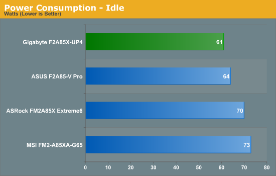
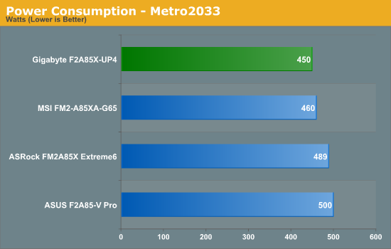
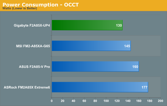
In the Power Consumption tests, it is clear to see the Gigabyte take a commanding lead. This should be derived from the efficiency of the power delivery used on board.
POST Time
Different motherboards have different POST sequences before an operating system is initialized. A lot of this is dependent on the board itself, and POST boot time is determined by the controllers on board (and the sequence of how those extras are organized). As part of our testing, we are now going to look at the POST Boot Time - this is the time from pressing the ON button on the computer to when Windows starts loading. (We discount Windows loading as it is highly variable given Windows specific features.) These results are subject to human error, so please allow +/- 1 second in these results.
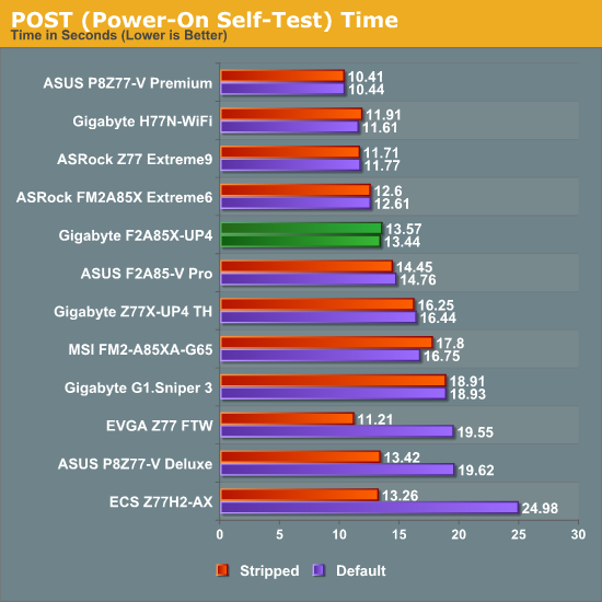
In the grand scheme of going through POST in our dual GPU scenario, we put an ideal line around 12 seconds for a great POST time. The Gigabyte F2A85X-UP4 just misses this, and attempts to reduce the time by disabling controllers had no effect. Compared to other FM2/A85X motherboards we have tested, only the ASRock is faster than the Gigabyte.
Rightmark Audio Analyzer 6.2.5
In part due to reader requests, we are pleased to include Rightmark Audio Analyzer results in our benchmark suite. The premise behind Rightmark:AA is to test the input and output of the audio system to determine noise levels, range, harmonic distortion, stereo crosstalk and so forth. Rightmark:AA should indicate how well the sound system is built and isolated from electrical interference (either internally or externally). For this test we connect the Line Out to the Line In using a short six inch 3.5mm to 3.5mm high-quality jack, turn the OS volume to 100%, and run the Rightmark default test suite at 48 kHz, 96 kHz and 192 kHz. We look specifically at the Dynamic Range of the audio codec used on board, as well as the Total Harmonic Distortion + Noise.
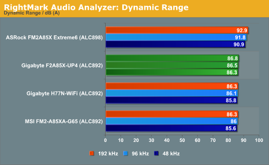
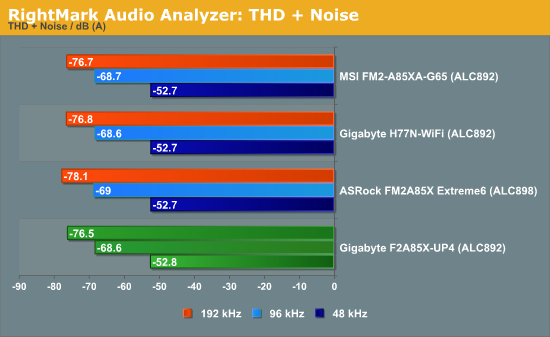
The ALC892 shows that the dynamic range offered (and constructed) in the ASRock product is superior to that of the other FM2/A85X models.
USB 3.0 Backup
For this benchmark, we run CrystalDiskMark to determine the ideal sequential read and write speeds for the USB port using our 240 GB OCZ Vertex3 SSD with a SATA 6 Gbps to USB 3.0 converter. Then we transfer a set size of files from the SSD to the USB drive using DiskBench, which monitors the time taken to transfer. The files transferred are a 1.52 GB set of 2867 files across 320 folders – 95% of these files are small typical website files, and the rest (90% of the size) are the videos used in the WinRAR test.
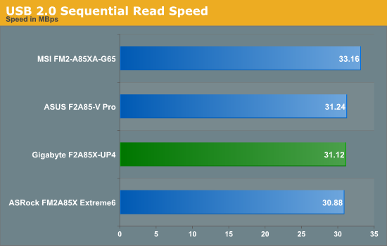
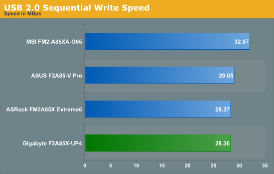
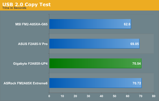
Despite the commanding lead of the MSI FM2 board (related to a BIOS setting that also interferes with Turbo modes), the Gigabyte performs middle of the pack with respect to the other FM2 motherboards on USB 2.0.
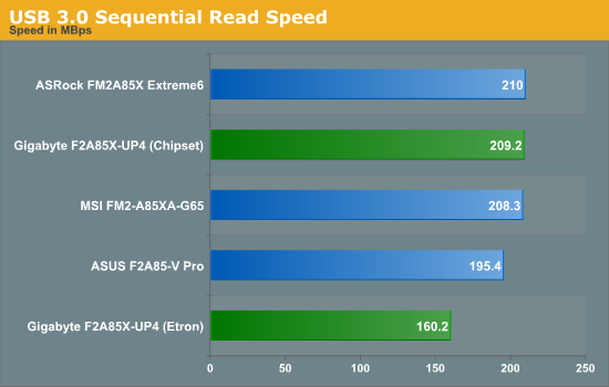
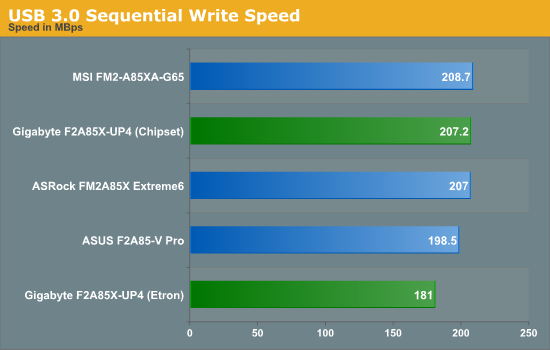
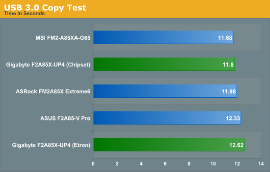
Consistency seems key on USB 3.0, with the Chipset ports coming second in all tests. The Etron controller on board has additional latency to contend with, but even with this the peak speeds (and overall usage test) fall by the wayside in comparison to the Chipset implementation.
DPC Latency
Deferred Procedure Call latency is a way in which Windows handles interrupt servicing. In order to wait for a processor to acknowledge the request, the system will queue all interrupt requests by priority. Critical interrupts will be handled as soon as possible, whereas lesser priority requests, such as audio, will be further down the line. So if the audio device requires data, it will have to wait until the request is processed before the buffer is filled. If the device drivers of higher priority components in a system are poorly implemented, this can cause delays in request scheduling and process time, resulting in an empty audio buffer – this leads to characteristic audible pauses, pops and clicks. Having a bigger buffer and correctly implemented system drivers obviously helps in this regard. The DPC latency checker measures how much time is processing DPCs from driver invocation – the lower the value will result in better audio transfer at smaller buffer sizes. Results are measured in microseconds and taken as the peak latency while cycling through a series of short HD videos - less than 500 microseconds usually gets the green light, but the lower the better.
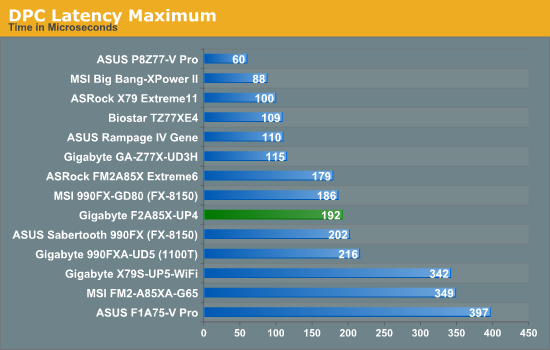
The Gigabyte F2A85X-UP4 stays under the 200 microsecond mark we normally consider a great result. Although it should be pointed out that there are still problems with the hardware monitor part of the EasyTune6 software, which as a result will make the DPC Latency spike up to 1000+ microseconds. For ideal usage under audio recording conditions, ET6 should be turned off.
3D Movement Algorithm Test
The algorithms in 3DPM employ both uniform random number generation or normal distribution random number generation, and vary in various amounts of trigonometric operations, conditional statements, generation and rejection, fused operations, etc. The benchmark runs through six algorithms for a specified number of particles and steps, and calculates the speed of each algorithm, then sums them all for a final score. This is an example of a real world situation that a computational scientist may find themselves in, rather than a pure synthetic benchmark. The benchmark is also parallel between particles simulated, and we test the single thread performance as well as the multi-threaded performance.
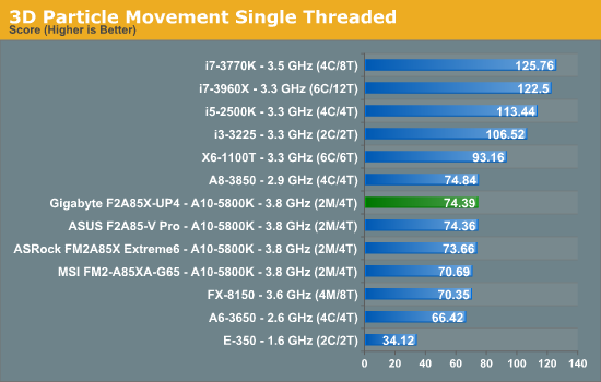
The Gigabyte F2A85X-UP4 seems to have no trouble ramping up to full turbo mode in our single threaded floating point test. It marginally comes ahead of the other FM2 boards, but the gap is within the margin of error.
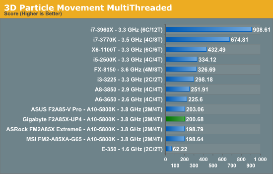
To continue with Gigabyte’s run of being in the pack, our multithreaded floating point test places the board in second place. The gap to the ASUS board seems a little larger than expected.
WinRAR x64 3.93 - link
With 64-bit WinRAR, we compress the set of files used in the USB speed tests. WinRAR x64 3.93 attempts to use multithreading when possible, and provides as a good test for when a system has variable threaded load. If a system has multiple speeds to invoke at different loading, the switching between those speeds will determine how well the system will do.
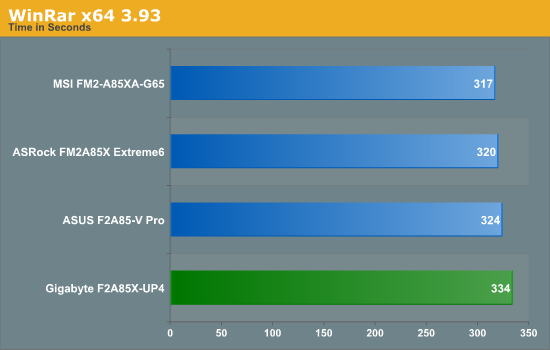
Despite the words above, out WinRAR test on the F2A85X-UP4 was a little disappointing being 17 seconds (~5%) behind the top placed FM2/A85X motherboard.
FastStone Image Viewer 4.2 - link
FastStone Image Viewer is a free piece of software I have been using for quite a few years now. It allows quick viewing of flat images, as well as resizing, changing color depth, adding simple text or simple filters. It also has a bulk image conversion tool, which we use here. The software currently operates only in single-thread mode, which should change in later versions of the software. For this test, we convert a series of 170 files, of various resolutions, dimensions and types (of a total size of 163MB), all to the .gif format of 640x480 dimensions.
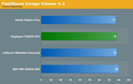
Despite the WinRAR result, the Gigabyte stays in the pack in single threaded Faststone.
Xilisoft Video Converter
With XVC, users can convert any type of normal video to any compatible format for smartphones, tablets and other devices. By default, it uses all available threads on the system, and in the presence of appropriate graphics cards, can utilize CUDA for NVIDIA GPUs as well as AMD APP for AMD GPUs. For this test, we use a set of 32 HD videos, each lasting 30 seconds, and convert them from 1080p to an iPod H.264 video format using just the CPU. The time taken to convert these videos gives us our result.
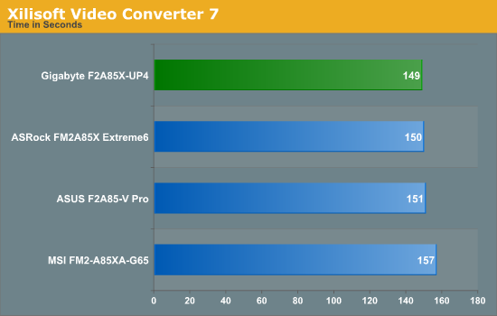
Despite the previous differences we saw in multithreaded testing, as Xilisoft uses an integer work load, we can really stretch the legs on Bulldozer-derived processors. The Gigabyte takes the lead in this test.
x264 HD Benchmark
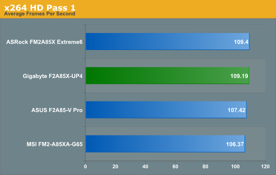
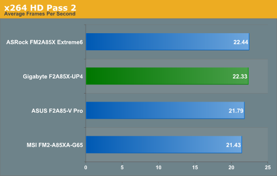
The x264 HD Benchmark uses a common HD encoding tool to process an HD MPEG2 source at 1280x720 at 3963 Kbps. This test represents a standardized result which can be compared across other reviews, and is dependant on both CPU power and memory speed. The benchmark performs a 2-pass encode, and the results shown are the average of each pass performed four times.
Metro2033
Metro2033 is a DX11 benchmark that challenges every system that tries to run it at any high-end settings. Developed by 4A Games and released in March 2010, we use the inbuilt DirectX 11 Frontline benchmark to test the hardware at 2560x1440 with full graphical settings. Results are given as the average frame rate from 4 runs.
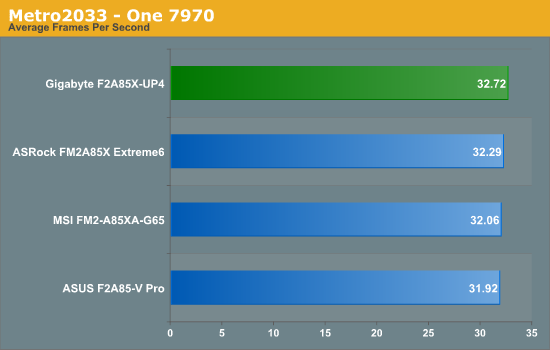
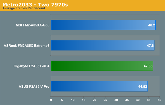
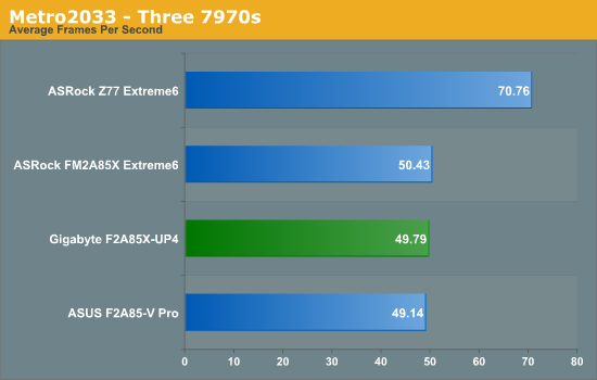
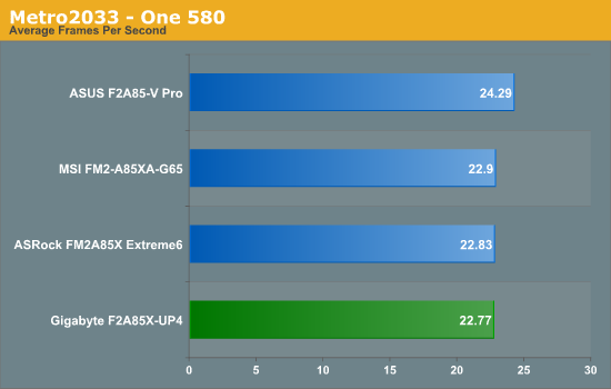
Performance under Metro is consistent with most other motherboard testing.
Dirt 3
Dirt 3 is a rallying video game and the third in the Dirt series of the Colin McRae Rally series, developed and published by Codemasters. Using the in game benchmark, Dirt 3 is run at 2560x1440 with Ultra graphical settings. Results are reported as the average frame rate across four runs.
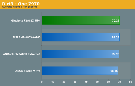
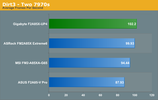
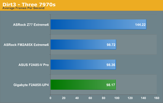
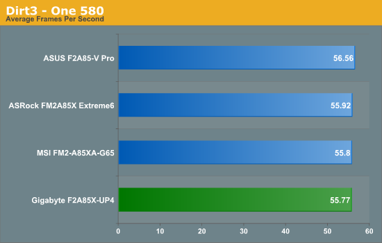
While it seems that the Gigabyte takes the top spot in single and dual GPU for Dirt 3 and then bottom for tri-GPU and NVIDIA, all results are within the margin of error to other FM2/A85X motherboards, except that dual GPU result. Unfortunately I cannot attribute why there would be so much discrepancy, especially when in other tests this type of variation is not shown.
During the testing of a motherboard, anything that seems out of the ordinary or is not default behavior compared to a normal usage scenario gets noted down in my lists under the benchmark results. It gives a point of reference for me when it comes to writing the review and tells you guys and gals how I felt about the product. Looking back on my notes now and simply put, there are none. The Gigabyte F2A85X-UP4 just worked out of the box without issues and no abnormal behavior. This is an oddly surreal experience, especially in my line of work.
Working normally is not grounds for an award, I should make that clear. Working normally should be the standard by which all boards are judged – everything should work as intended anyway. To give something an award for ‘working normally’ is to do injustice to an award system and devalue the importance it has on driving innovation. Innovation is a key word in the motherboard industry, and each manufacturer should be trying their hardest to provide something new to the table that no-one else does. Price is also another key word, which ultimately decides the fate on almost everything apart from halo products.
The Gigabyte F2A85X-UP4 is currently on sale for $130 at Newegg, some $10 cheaper than the ASUS F2A85V-Pro high-end model we reviewed, but $20-$25 more expensive than the ASRock FM2A85X Extreme6 and MSI FM2-A85XA-G65 we have also reviewed. For that money, as mentioned previously, we get PowIRStage IR3550 ICs in the power delivery, which are not exactly cheap. Video outputs come via each one of the four major outputs on offer today – D-Sub, DVI-D, HDMI and DisplayPort; audio and network use the Realtek ALC892/8111E combination often sold in bulk and at a discount when purchased together to motherboard manufacturers. The eight SATA 6 Gbps ports of A85X are split such that 7 are on the board as normal SATA ports and one becomes an eSATA – a slightly different tack than the mSATA variations we saw in the Gigabyte Z77 release. Aside from the normal USB ports on board we get an Etron EJ168 USB 3.0 controller for another pair of USB 3.0 on the back panel. Power/Reset buttons and a two-digit debug LED are always welcome.
The Gigabyte eco-system on their main lines of motherboards and chipsets revolve around the 3D-BIOS implementation, which is a way of saying ‘we use an oblique image in our BIOS’. I have critiqued the Gigabyte 3D BIOS system previously, noting its failings, both to our readers and directly to the people at Gigabyte who make these decisions. While the BIOS works, in my view it is not the easiest system to use for beginners, enthusiasts nor overclockers – small updates like a tooltip when hovering over the SATA ports, or actually telling the user what model motherboard they have on the front entry screen are some suggestions I have made. In the case of the F2A85X-UP4, based on the typical 3D-BIOS, I did not find anything to change my viewpoint of the system, but all the options I tried did work and was happy to do so.
The software package on board is still based around EasyTune6, except this time we are devoid of automatic overclock options. One small flaw is that the older versions of EasyTune6 fail to work in the presence of CPU-Z, and that as noted on previous Gigabyte models, EasyTune6 will disrupt DPC Latency, and thus for audio/video processing it may be advised to switch ET6 off while recording.
Performance of the F2A85X-UP4 is in line with the other FM2/A85X boards we have tested. The Gigabyte model seems better in terms of power consumption at the wall in all scenarios under our testing with two GPUs installed. Our IO and gaming tests did not pull anything out of the ordinary in terms of results; however the ultimate overclock was a little disappointing in only achieving 4.5 GHz on default LLC. In the box however is an assortment of six SATA cables ready to use, more than any other vendor so far in our Trinity/A85X coverage.
While overall a good product to have, and we have praised the IR3550 power delivery before, there is nothing else to make this motherboard stand out from the competition. The added effect of the IR3550s pushes the price to $130, but the extra expense may give a user piece of mind that the power delivery is cooler and should ultimately last under high-stress scenarios. It is certainly an important board to consider in the Trinity motherboard space and if our testing is anything to go by, and it should be a reliable purchase if your usage scenario comes close to ours.

